Need to understand how to read performance curves? Looking to learn about the differences between multiple impeller designs? Ever been curious how centrifugal pumps came to be?
No problem! That’s why we created this comprehensive centrifugal pump guide.
Despite the fact that we still use them today, it might surprise you to know that centrifugal pumps have been around for more than 300 years. In 1687, French physicist Denis Papin developed the design for the first true centrifugal pump and the rest is
history.
In 1849, nearly 200 years after Papin’s invention, the first all-metal centrifugal pump came onto the market. Two years later, British inventor John Appold saw a need to better displace fluid, and so he created the design for the curved vane impeller.
It’s worth noting that, despite optimization changes like the use of metal and a shift in impeller structure, the overall design for the centrifugal pumps we use today are very similar to the original design created by Papin three centuries ago.
While there is some variety and slight differences when it comes to centrifugal pump designs, most operate in a relatively similar fashion. This example will show how a close-coupled, end suction pump functions.
- The suction flange takes fluid into the pump and the discharge flange sends it out with higher head than when it entered.
- Using either electric, hydraulic, or diesel energy, the driver motor powers the shaft that rotates the impeller.
- The veins of the impeller rotate and throw the fluid, accelerating it and imparting heat energy.
- The higher velocity fluid is then accelerated into the case.
- The higher energy accelerates it into the casing geometry for further direction.
- The case then collects and decelerates the fluid, converting some velocity head into pressure head.
- Then the fluid is discharged with high head.
- This process repeats as fluid is constantly pulled in, allowing for continuous energy to be imparted to the fluid.
Centrifugal pumps can be broken down into a handful of types, each with their own variants.
Overhung Pumps
Overhung pumps are those where the shaft is only providing support to the impeller from a single side. Overhung pumps can be further broken down based on the type of coupling used to transfer power from the motor to the pump itself.
- Flexibly Coupled: the pump is mounted on a base plate that requires a motor to be attached to that same plate support structure. A flexible coupling passes power from the motor to the pump.
- Rigidly Coupled: the pump and motor are tightly aligned with a structure or bracket, and the coupling is rigid – meaning that misalignment is difficult to fix. These kinds of pumps must be assembled carefully and accurately as to avoid misalignment.
- Close Coupled: the impeller is directly mounted on the motor shaft with no coupling required.
Once you’ve determined the type of coupling in the overhung pumps, you can further classify them based on the vertical or horizontal mounting.
Between Bearing Pumps
Between bearing pumps differ from their overhung counterparts in that the shaft has bearing support on both sides instead of one. In these types of pumps, the impeller is positioned in the middle of the
shaft, between the two supports.
Between bearing mounts are typically used for higher energy/higher flow pumps because the high radial loads the impeller provides necessitates the need for greater support.
Vertical Turbine Pumps
Vertical turbine pumps, also known as deep well turbine pumps or line shaft turbine pumps, are purpose built to move water out of long, tight vertical spaces like underground wells and reservoirs.
Just like the pumps themselves, impellers can be divided into different categories based on the application at hand.
Closed
Closed impellers feature a protective shroud on both the front and back. These shrouds allow for greater control of flow passage, making them desirable for hydraulic efficiency.
However, that same shroud means that the internal flow path can wear away over time, particularly in operations working with abrasives or corrosives. The smaller internal pathway also makes it harder to operate with solids, since they might get stuck
and cause hydraulic imbalances. As such, closed impellers are mostly used for clean fluid applications.
Semi-Open/Open
Semi-open or open impellers lack the protective shroud of their closed counterparts. This means they must be installed close to the casing itself – which acts as the front shroud for impellers of this type.
The gap between the impeller and casing means this type of impeller isn’t as efficient as the closed variety. However, solids run more easily through open impellers since they wear themselves down against the casing, allowing them to pass through.
Although the impeller type indicates how a pump will generally perform, it’s the specific impeller design that defines the hydraulic performance. This value is the specific speed, a dimensionless theoretical quantity that characterizes pump performance
(head, flow, speed) and is determined at the pump’s best efficiency point (BEP).
Predicting how your pump will operate under specific conditions is helpful for any operation. That’s where pump performance curves – charts that allow you to determine a pump's ability to produce flow under the conditions that affect pump
performance – come in handy.

While a pump performance curve might look daunting at first, we’ll break down how to read each part of this chart in detail.
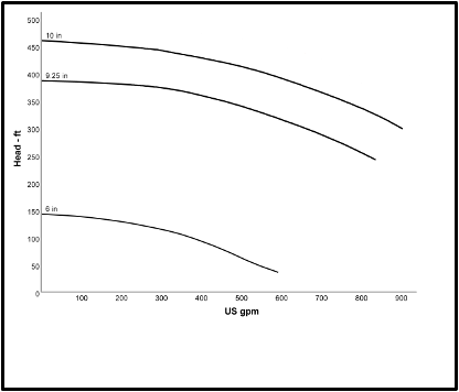
To start, note that the left-hand vertical axis measures the pump’s head in feet and the horizontal axis charts its flow in gallons per minute (gpm). Plotting a point between these values allows pump operators to predict how much head a pump will
generate at a specific flow rate. The black line shown represents a pump’s specific impeller trim – for this chart, it’s 10”.
The right-hand vertical axis comes into play when calculating a pump’s BEP. This axis represents how efficient the pump will be at different flow rates. The light blue line represents the efficiency of a pump with a 10” impeller trim, and
peaks around 73%, the ideal operating conditions for that pump.
The red line represents the pump’s power requirements. It is plotted against a third vertical axis, typically horsepower or kilowatts.
The dark blue line below the chart represents the pump’s NPSHr to make sure it isn’t cavitating. It is plotted against a fourth vertical axis and is measured in feet.
To interpret a pump performance curve, draw a vertical line through the impeller trim line down to the flow rate at any given point. You can then read the characteristics where the line crosses the other curves to determine how the pump will perform at
that flow rate.
Generally speaking, moving left means higher heads, lower HP and lower NPSHr. A pump’s efficiency may get better or worse moving either direction, depending on best operating conditions.
Pump affinity laws are highly accurate for small changes to pump performance. To best predict how a pump will perform under a large change, you should rely on test data.
For that reason, composite pump performance curves – published data sets from pump manufacturers – exist to allow pump operators to better understand how their equipment will perform when run with varying impeller diameters or pump speeds.
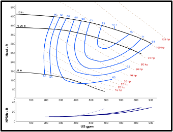
These curves show the pump head, efficiency, power, and NPSHr values for varying flow rates plus another variable, such as impeller trim or pump speed. They also typically include the minimum impeller trim the pump is designed to work at.

A typical composite curve shows multiple trim sizes on the same graph, as pictured above.
Efficiency on these charts is shown with iso-efficiency lines – the arcing blue lines running between the lines for different impeller diameters that show how efficient each trim would be when run at that flow rate.
Power lines are also shown as iso-power lines – the dotted lines running diagonally across the graph.
To read these curves, start by picking a single point on any of the lines for impeller trim. From that dot, draw a vertical and horizontal line to each axis to determine how much head the pump is generating and what gpm it’s running at.
To determine best efficiency, interpolate between nearest iso-efficiency lines – pick the line that is closest and interpret what the actual efficiency is. For example, if the dot is close to 73% efficiency, the real value might be somewhere around
72.8%.
Then, do the same between the nearest two iso-power lines to determine the horsepower of the selected point.
To determine NPSHr for the selected point, extend the vertical line from your dot down to the section of the chart dealing with NPSH and the point where it crosses represents the NPSHr for the selected impeller trim.
The BEP holds importance beyond simply being the point at which a pump is most efficient. Running pumps at their BEP also means that they will be operating with the lowest radial loads and lowest vibration levels possible.
Pumps that run at their BEP are the most reliable. Moving away from the BEP leads to increased thrust load on the shaft, meaning more energy will be consumed and more vibrations could occur.
Pump manufacturers will usually provide a range for a pump’s BEP, but the preferred operating range for most centrifugal pumps is 70-120% of the BEP for specific speeds less than or equal to 4,500.